


Testing High-Speed Active Electrical Cables (AEC) for AI Servers

2025-07-15
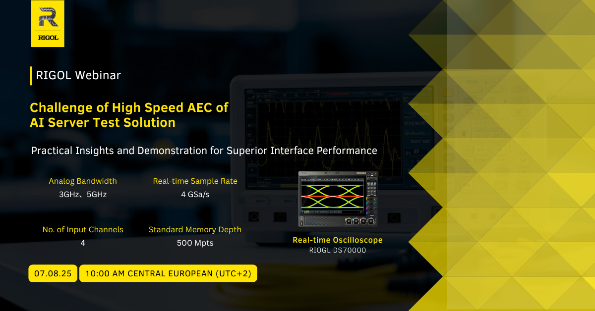
Testing High-Speed Active Electrical Cables (AEC) for AI Servers – Challenges, Methods and a Real-World Case
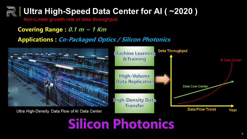
The Market Trend & Status of AI Servers
AI data centers differ sharply from traditional, mobile-driven facilities. Machine-learning training, massive data replication, and ultra-dense in-rack traffic make throughput grow exponentially, not linearly. One planned site in Louisiana is budgeted at USD 10 billion and will rely on nuclear power to feed 100 k servers, 10 k switches, and more than one million optical nodes. Industry reports project ≥15 % CAGR and an aggregate 19.5 zettabytes by 2030. Interconnect bandwidth—rather than compute—has become the primary bottleneck.
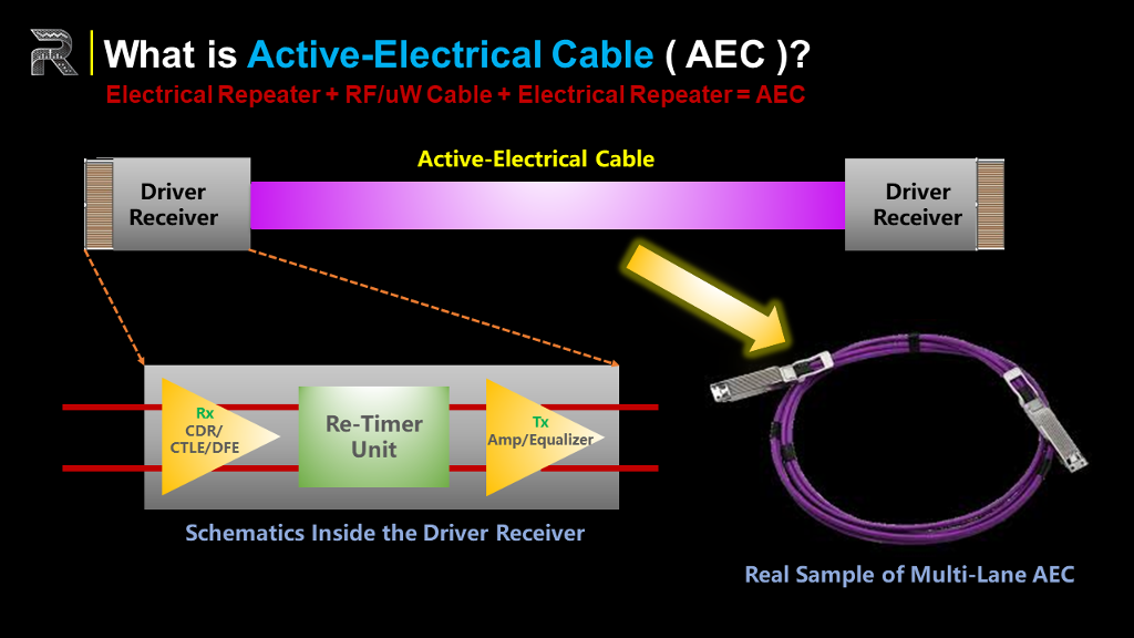
What is the AEC?
Long (kilometers) or middle (hundreds of meters) reaches still rely on pluggable optics or silicon-photonics transceivers. For short links inside a rack (< 3 m) or tray (~ 7 m), full optical chains are unnecessarily expensive because lasers, drivers, modulators, and TIA/PDs dominate cost and power. The industry therefore inserts copper-based alternatives:
• DAC: purely passive copper, ≤ 3 m
• AEC: Active Electrical Cable, up to ~ 7 m
• AOC/fiber: ≥ 100 m
An AEC is a twin-ax copper bundle with active silicon—equalizer, CDR, retimer, and driver—at both ends. Current products carry 2/4/8 differential lanes for 200 G, 400 G, 800 G, and even 1.6 Tb/s aggregate bandwidth while cutting the cost of short-reach optics.
How to do the AEC Test?
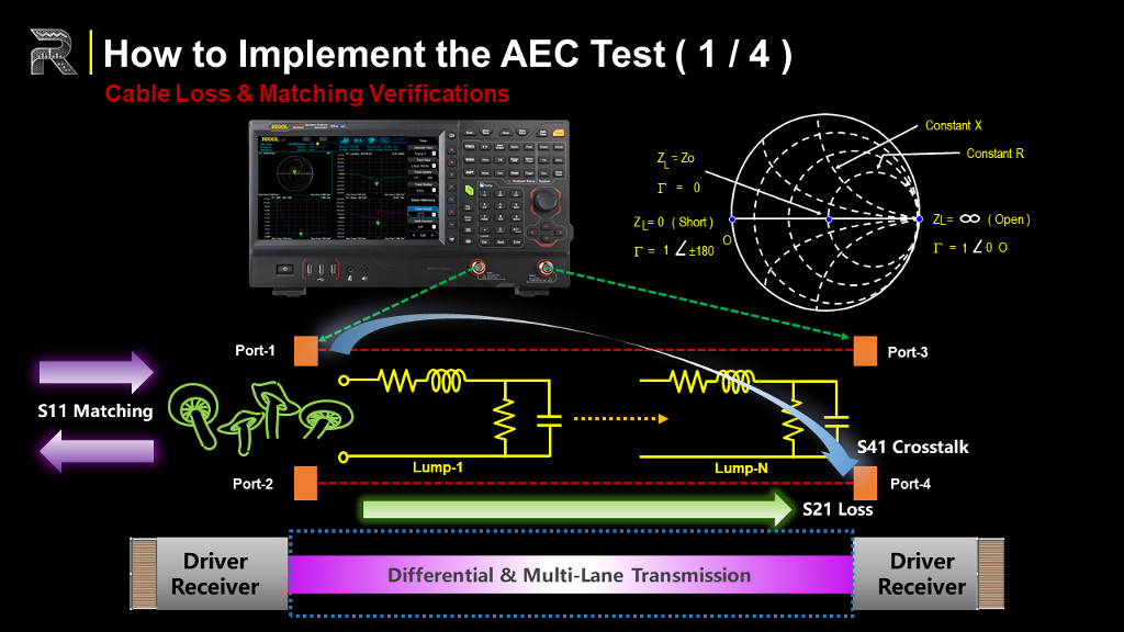
Frequency Domain – VNA on the passive section
• SDD11 (impedance match via Smith-Chart)
• SDD21 (insertion/return loss; target ≤–5 dB across band)
• S41 (near- and far-end crosstalk for multi-lane bundles)
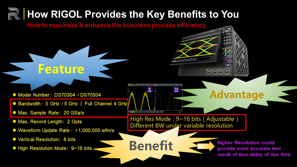
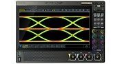
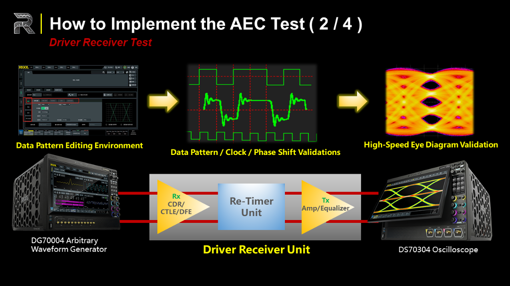
Time Domain – AWG + high-bandwidth Oscilloscope on the active section
• AWG (DG70000, 5GHz, 1.5Gpts, 16 bits)Step generator with <1 ps edge; 200 ps rise used in the demo
• Power divider: one leg to scope (reference), one through DUT
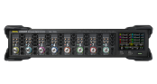
• Scope (DS70000, 5 GHz, 20 GS/s, 2 Gpts, 9-16 bit mode) captures propagation delay and phase shift—example result ≈15 ns—to feed back into the retimer.
• Accumulated eye diagrams, jitter, and mask tests validate equaliser performance.
Device Level – Bit-Error-Rate Test
• PRBS loop-back through the complete AEC
• IEEE 802.3ae / CEI limit BER ≤ 1 × 10⁻⁶

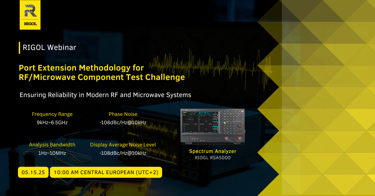
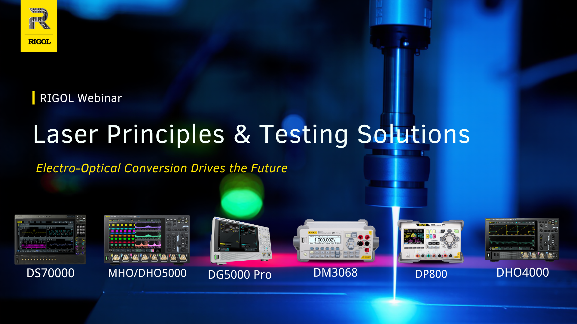
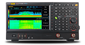
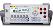
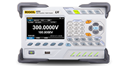
Supporting instruments mentioned in the webinar: RSA5000 with VNA option (S-parameters, DTF), DG-series AWGs (16-bit) for lower-speed patterns, low-ripple linear PSUs, DMMs and DAQ for multi-channel logging.
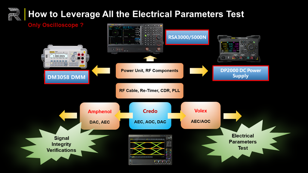
How to Leverage All the Electrical Parameters Test
Beyond the AWG, high-bandwidth oscilloscope, and VNA, a complete AEC evaluation still depends on conventional bench equipment. Linear DC power supplies provide clean, low-ripple rails during R&D and production, so that noise on the supply does not obscure signal-integrity results. Precision digital multimeters let engineers probe voltage and current at any node, verifying that every lane and device meets its operating limits. By combining these basic tools with the high-speed instruments already described, the test setup covers both advanced signal-integrity metrics and the fundamental electrical parameters required for a reliable AI-server interconnect.
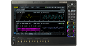
Recommended Oscilloscope Platform
A Python-controllable RIGOL oscilloscope with adjustable high-resolution mode lets engineers see fine waveform details and sub-picosecond edge shifts, delivering the delay and phase accuracy that high-speed AEC links require. Switching resolution on the fly streamlines signal-integrity checks and speeds overall validation, so development teams can present confident, customer-ready results.